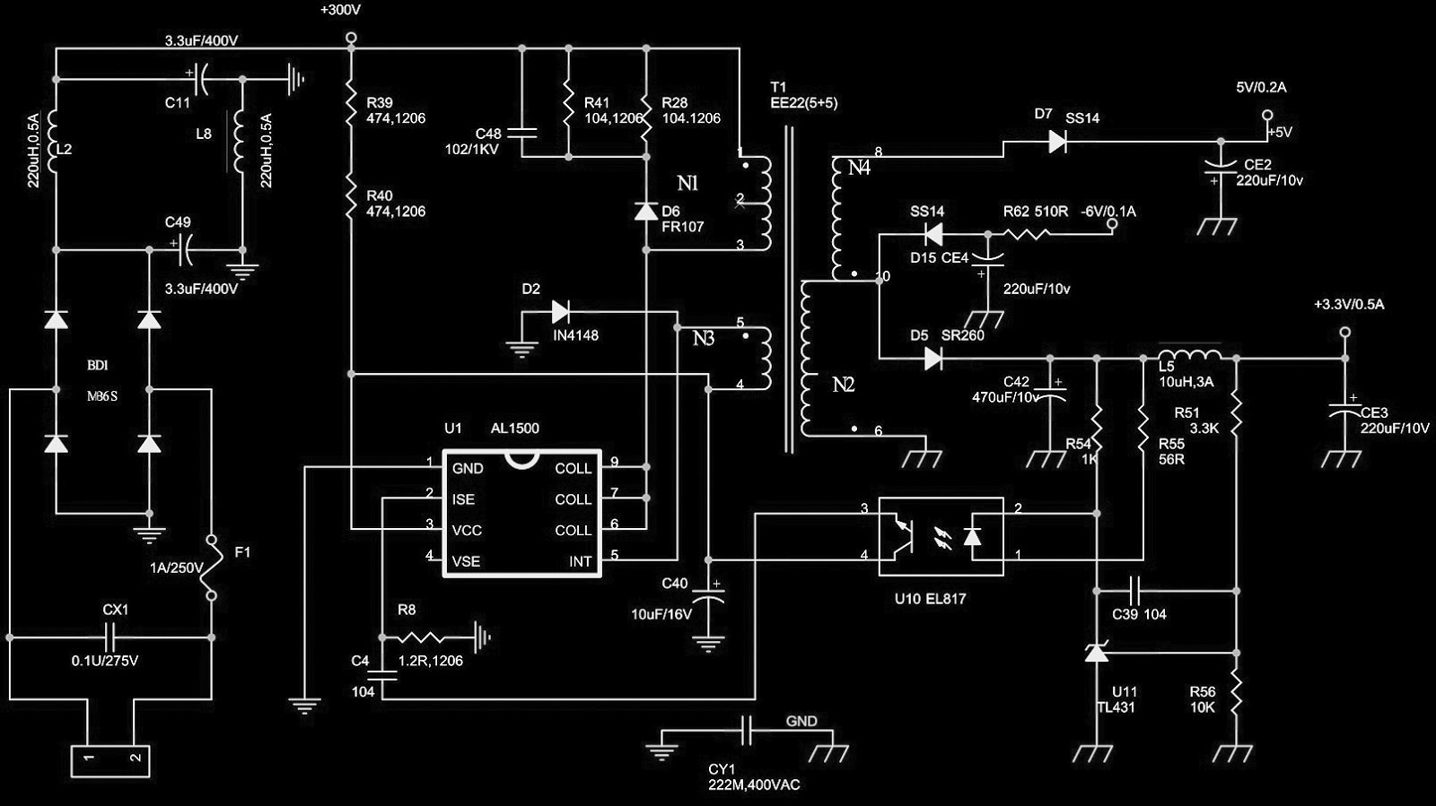
The functional diagram of one of the devices of the VIPer family is shown in Figure 1. The name VIPer comes from the manufacturing technology of the MOSFET itself, namely the Vertical Power MOSFET.
VIPER SMPS DESIGN SOFTWARE SERIES
STMicroelectronics, having analyzed the difficulties encountered in the design of switching power supplies, has developed a unique series of microcircuits, combining a PWM controller, protection circuits and a powerful output MOSFET transistor on a single chip.

Output circuit consisting of a diode bridge and filter capacitors.Īs you can see, the number of active components that make up pulse unit power supply reaches several dozen, which increases the overall dimensions of the device and, as a result, creates a number of problems during design and debugging. Circuits for stabilizing the output voltage.Ħ. Protection circuits (overvoltage, overtemperature, etc.)Ĥ. Input circuit (includes mains filter, diode bridge and filter capacitors).ģ. The main nodes of the classic circuit of a pulsed flyback power supply consist of the following blocks.ġ. These disadvantages also create inconvenience in diagnosing and troubleshooting faults.

Difficulty setting due to selection passive components in the harness of the PWM controller, in the protection circuit, etc. However, these power supplies have their drawbacks:Ģ. The efficiency of modern switching power supplies reaches 95%. Switching power supplies are not inferior to transformer power supplies, moreover, they are much more efficient. With the advent of all kinds of PWM controller microcircuits and high-voltage powerful MOSFET transistors, transformer power supplies were replaced by pulsed ones, therefore, the overall dimensions and weight of the power supplies decreased several times. The mass of such a power supply unit will be about 5-7 kg, and there is nothing to say about its dimensions. Imagine a transformer power supply with an output power of 100-150 W, even made on a toriodal magnetic circuit. Visit the Tape Wound Cores page to learn more about Magnetics’ strip wound cores, amorphous cut cores, and nanocrystalline cores.In the recent past, many manufacturing companies began to abandon transformer power supplies due to their considerable weight and significant overall dimensions. While nanocrystalline cores are annealed to create a uniform microstructure, amorphous cut cores have an amorphous atomic structure, resulting in higher resistivity than nanocrystalline. Among Magnetics’ strip wound products are also high permeability nanocrystalline cores and amorphous cut cores, both made from metallic glass materials. Magnetic strip wound cores, or tape wound cores, are crafted from thin strips of high permeability nickel-iron alloys that are wound into toroids for varying frequency applications, including current transformers, pulse transformers, output transformers, magnetic amplifiers, and more. Visit the Ferrite Cores page to learn more about this type of core. Ferrite cores can be machined to custom specifications in order to meet individualized operational requirements. Because of these properties, ferrite cores are commonly used for high-frequency power transformers, power inductors, radio frequency transformers, EMC filters, current sensors, and more.Īs is with powder cores, Magnetics’ ferrite cores are available in numerous industry-standard shapes and sizes and are offered alongside some hardware and accessories. The benefits of employing ferrite cores include high magnetic permeability and low electrical conductivity, helping to prevent eddy currents. Magnetics ferrite cores are made from manganese zinc (MnZn). Ferrite Coresįerrite cores are dense, ceramic shapes that are crafted from a mix of iron oxide and other metal oxides or carbonates, such as magnesium, zinc, or manganese. Visit the Powder Cores page to learn more about this type of core. For this reason, they are commonly used for high current/low ripple applications, including (but not limited to) flyback transformers, resonant circuits, battery chargers, loading and choke coils, as well as boost and output inductors. These cores are widely utilized for their high electrical resistivity, low hysteresis and eddy current losses, low permeability changes in high temperatures, and significant inductance stability in both AC and DC environments. Powder cores are created using the powder of multiple alloys with distributed air gaps to help condense their magnetic fields and minimize core loss. These components can be categorized as follows: Powder Cores

Magnetics produces a multitude of soft magnetic components, each lending themselves to specific applications based on their unique properties. Magnetic cores are produced from materials featuring high magnetic permeability and are used in a wide variety of electrical, electromechanical, and magnetic equipment.

Soft Magnetic Components: Powder Cores & More


 0 kommentar(er)
